Frequently Asked Questions
ReaderRouter™
Which ReaderRouter™ model do I need?
What's the difference between a ReaderRouter and ReaderHub?
How do I power the ReaderRouter?
What criteria can I use to do routing?
How do I route based on facility/site code?
How do I route based on the number of bits in the format?
Does the ReaderRouter support HID's Corporate 1000 or other long codes?
Where do unrecognized swipes go?
Can I send swipe data to more than one controller?
Can I reprogram at the job site?
How do I control the rest of the door signals?
AccessEmulator™
What does the AccessEmulator actually do?
What format codes are supported?
Do I need a PC to run the AccessEmulator?
Can the AccessEmulator run automatically?
How do I set up a test?
Can I make the unit test regions?
What about anti-passback or 2-man rules?
How do I simulate lots of activity?
What kind of readers can I connect?
Which ReaderRouter™ model do I need?
There are two models of ReaderRouter - the 8-port and the 4-port. This difference refers to the number of outputs on the ReaderRouter. Both models support two card readers. You will need to choose a model with enough outputs to support the number of controllers X the number of readers it will support. For instance, if you are supporting one door (reader), you can connect up to 8 different controllers using the 8-port ReaderRouter. With two doors connected, you can connect to 4 different controllers.
What's the difference between a ReaderRouter and ReaderHub?
The main difference between the ReaderRouter and ReaderHub is that the ReaderRouter can selectively route card swipes to different outputs based on a number of different criteria. The ReaderHub always sends card swipes to the outputs. Depending on how you set the ReaderHub's jumper, it will either send all inputs to all outputs or it will send input 1 to the lower numbered outputs and input 2 to the upper outputs.
How do I power the ReaderRouter?
The ReaderRouter (or ReaderHub) is powered from 12V DC. Typically this is from the same supply as the card reader or is sourced from one of the the controllers. The power input can support a range of 9V to 24V DC.
What criteria can I use to do routing?
You can route cards based on:
Facility code
Card number (or range of numbers)
Number of bits
..combination of the above
When a match is made, that swipe is sent to the outputs selected by that rule.
How do I route based on facility/site code?
To route based on the facility code, there are two basic steps:
1 - Define the format and what bits in the format correspond to facility code.
2 - Create a rule using that definition to test is the swipe should be routed.
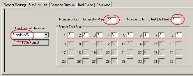
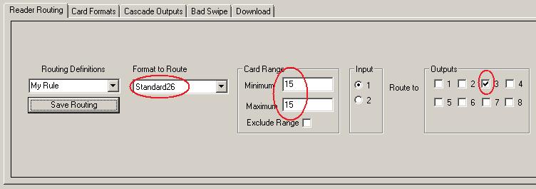
The following is an example for routing all cards with facility code = 15 to the 3rd output. In this example, standard 26-bit weigand format is used. In the first screenshot below, we define a standard 26-bit card format in which the 8-bit facility code to extract [test] is located in bits 2-9. We have arbitrarily named this format Standard26. You can choose whatever is convenient for your site.
In the second screenshot below, we have create a rule that says:
For any card that matches the
length of Standard26, AND has a facility code of 15, send it to output 3.
For standard 26-bit weigand, we've created a Wiegand Calculator to help out with decoding formats.
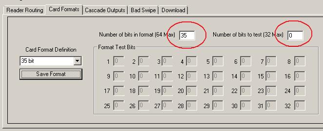
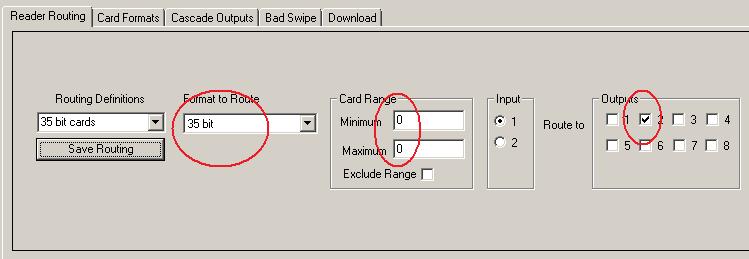
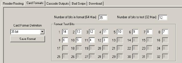
How do I route based on the number of bits in the format?
This is a quick way to set up routing if one of the tenants' cards have a different number of bits than the others. You can route those card swipes based solely on the number of bits in the format. In the example below, we'll assume most cards are 26-bit, but you have one tenant using 35-bit cards that you want to send to output 2. To do this, first define a format that is 35 bits long, but doesn't test the bits for value:
Next, you create a rule to route any matching swipes to that output (output 2) by selecting the desired format, without specifying a card range.
Does the ReaderRouter support HID's Corporate 1000 or other long codes?
The ReaderRouter supports card swipes of up to 64 bit length. This means that it can work with the Corporate 1000 type format. There are a couple of things to note.
First, the ReaderRouter can only examine and making routing decisions based on 32 bits of information. This means that while it will properly pas up to 64 bits of card data to the controller, it will only use up to 32 of those bits for a routing decision.
Second, the spec for Corporate 1000 format allows different customer-specific "recipes". The facility and card codes can appear in different places within the card swipe for different customer-specific versions of the format. One common implementation of a 35 bit format has the facility code in the 3rd through 14th bits. To set up routing by that facility code, you would define the format as shown here:
If your cards use a different recipe, you'll need to make sure you know where in the bit field the data you need to test is located. If only one building tenant is using a certain swipe length, you don't even need to decode it - just pass all swipes of that length to the output assocaited with that tenant's controller. See the related question for an example of routing by format length.
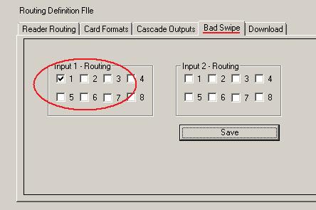
Where do unrecognized swipes go?
Unrecognized swipes get sent to whatever output(s) are selected on the Bad Swipe tab in the RRConfig tool. Note that these swipes are not necessarily bad. All this means is that the swipe didn't meet the rules set for any routed swipes.
This can be a handy way to set default routing. For example, if you wanted cards with a facility code = 240 to go to output 2, but ALL OTHER cards to be sent to output 1, you would create a routing rule to send facility code = 240 to output 2 using the Reader Routing tab, and then go to the Bad Swipe tab and select output 1.
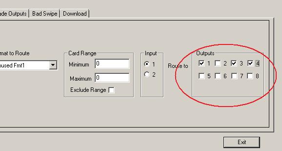
Can I send swipe data to more than one controller?
Card swipes that come in to either input can be routed to any number of outputs. Typically, you would send some cards to one controller and some to another, but there may be some cards that should go to more than one controller. These could include building security or maintenance personnel or emergency responders. To do this, just select (with checkboxes) which outputs to send to as shown here:
Can I reprogram at the job site?
Routing definitions can be easily downloaded to the ReaderRouter onsite using the included RRConfig software tool. You'll need a laptop or other Windows-based PC and a USB-to-RS232 adaptor. You can also upload from a ReaderRouter to your PC.
Even though downloading is easy to do in the field, we recommend that you set up the routing and format definitions and test things out in the shop ahead of time. That way you're not trying to figure out those details in a utility closet or with an audience.
How do I control the rest of the door signals?
Note that the ReaderRouter (and ReaderHub) only impact card reader signals - not door control or supervision signals.
The most typical application - a door shared by the building system and a tenant's controller - is as follows:
For each shared card reader, the reader wiring (Wiegand) is connected to the ReaderRouter's input. One of the ReaderRouter's outputs is connected to the building controller's reader input and the other ReaderRouter output is connected to the tenant controller's reader input.
For the building system's cards, the ReaderRouter sends the swipe to the building controller to make the access decision and unlock the door.
For tenant cards, the ReaderRouter sends the swipe to the tenant's controller to make the access decision. If the card is authenticated, the tenant controller then requests that the door be opened by asserting an output (or contact closure) that is connected to an input (programmed input or REX) on the building system. The building system essentially treats this as a Request To Exit [REX] on the shared door. By connecting this way, the building system still retains final control over the door - the tenant system is responsible for authenticating tenant cards; the building system "owns" the door.
A less common way to configure the doors is to allow each controller to access the common door latch (their outputs would be either wire OR'ed or diode OR'ed together). A complication of this method is that you must then bypass the opposite system's door switch - otherwise it appears as a "door forced" event. That's why installers often configure using the first method.
AccessEmulator™
What does the AccessEmulator actually do?
The AccessEmulator simulates the activity of up to four doors, as seen by an access control system. Each door in this simulation consists of one card reader (wiegand output), a REX switch (request to exit), a door status switch (i.e. open/closed detection) and a door strike. The 3 access system inputs (reader, REX, status) are outputs from the AccessEmulator. The 1 access system output (strike) is an input to the AccessEmulator.
The AccessEmulator generates simulated card swipes, open and close activity on the door and REX activation. All of this activity is controlled by a list of sequence steps that can be programmed into the AccessEmulator using a Windows-based tool. Each of the 4 doors has its own list of sequence steps, so you can simultaneously run different activities on up to 4 doors.
The AccessEmulator can operate stand-alone because it stores card and sequence data in non-volatile memory. If you want to monitor operation, all activity can be seen on the RS232 port (using a PC with a terminal emulator – like HyperTerm) or on your PDA device using the infrared link.
What format codes are supported?
The AccessEmulator allows you to define up to five format codes, for use in generating simulated card swipes. Within a given format, you can define how many bits there are, which bits are card number, facility code, and other fields. You can also define if parity bits are present and how parity is calculated.
Formats of up to 64 bits can be defined for cards. In addition, if you are unsure of the details of a format code, but have an example card, the AccessEmulator can take a “snapshot” of up to five different cards that can then be used during simulation.
If you are using a defined format, you can program the AccessEmulator to step through a range of card numbers sequentially, to verify system response.
Although the current software version supports a large range of possible formats, there may be applications that require customized software. Please contact support@ccdesignworks.com for further information. Our developers are able to provide customized solutions at reasonable rates.
Do I need a PC to run the AccessEmulator?
No, the AccessEmulator is able to run as a stand-alone test system. A PC is recommended for defining card data and formats and is required to program the sequencer (but not needed for running the sequencer). Some setup and programming can be done using a PDA as a terminal, if a PC is not practical. This is sometimes a useful way to make minor changes when you are using the AccessEmulator in cramped quarters (like a customer installation).
The PDA also provides an easy way to monitor AccessEmulator activity in places where a PC is not practical.
The AccessEmulator Programmer (aep.exe) is a Windows-based tool that allows you to quickly set up the AccessEmulator, define cards and formats, and enter program data for the sequencer. This is also the tool that you would use to load and save these settings from/to files on your PC.
Can the AccessEmulator run automatically?
The AccessEmulator has a sequencer associated with each of the four doors that are simulated. The sequencer is essentially a program interpreter which steps through a list of up to 16 program steps as it simulates door activity. There is some very simple program control – such as the ability to repeatedly loop a step or a series of steps – but this sequencer is not intended as a general-purpose controller. There is no need to know any programming language to set up the sequencer.
For a given door, the sequencer executes a step to completion and then moves on to the next step. (Each door’s sequencer is independent, so there’s no forced linkage between activity on one door and activity on another.)
A typical example of a sequence step is the Valid Swipe, Open command. When the sequencer gets to this step, it will cause a card swipe to be simulated, and will then wait for the access system to energize the door strike. If a strike is seen, the AccessEmulator then opens the door, waits and closes the door. The AccessEmulator monitors the system and will either report the ongoing activity or will display an error condition if unexpected activity is seen. (In this example, the AccessEmulator would interpret the lack of a door strike within a pre-defined time as an error.)
Other possible sequence steps include:
- Stop
- Valid Swipe, Open
- Valid Swipe, Held Open
- Valid Swipe, Not Open
- Invalid Swipe
- REX, Open
- REX, Held Open
- Forced Open
- Wait for x Minutes
- Wait for Alarm
- Loop to earlier step
- Wait for Manual swipe
- Wait for Step x on another door
It depends what you are trying to test… The simplest test setup would be to use the AccessEmulator to emulate a single door. For this, you would hook the AccessEmulator to the access control system as if it were a real door. In other words:
-
The AccessEmulator’s wiegand data outputs connect to the access control system’s reader inputs.
-
The AccessEmulator’s REX output connects to the access control system’s REX input.
-
The AccessEmulator’s door switch output connects to the access control system’s door input.
-
The access control system’s strike output connects to the AccessEmulator’s strike input.
You can then apply power and start the AccessEmulator running its predetermined sequence of simulated door activity. Typically, you would then monitor your access control system to see that it is operating in an expected manner in response to the door activity. See the question above for more explanation of how the sequencer works. (The user manual goes into much further detail - these FAQs are intended to provide potential users with a basic understanding of the AccessEmulator’s capabilities.)
Can I make the unit test regions?
Doors can be grouped into regions by using the sequencers’ ability to cross-link activity between doors. This allows you to set up a sequence in which a cardholder enters a region through Door 1 and then leaves the region through Door 2 at a later time. The basic flow for this is shown here:
| Door 1 Sequence | Door 2 Sequence |
| step 1: Valid swipe, open | step 1: Wait for door 1, step 2 |
| step 2: wait 2 minutes | step 2: Valid swipe, open |
More complex activities within regions can be set up in a similar manner. You can have multiple cardholders enter a region before anyone leaves, or test max region occupancy rules, etc.
What about anti-passback or 2-man rules?
As in the region example above, careful planning of sequence steps can allow verification of various site policies.
How do I simulate lots of activity?
In testing access control systems, it is often difficult or prohibitively expensive to test a system in which there is a heavy load of activity (as might occur during shift change at a commercial facility). Each AccessEmulator allows you to simulate different activity on 4 doors simultaneously. There are system configuration variables that allow you to set the time delay between events. These can be set to relatively small values in order to maximize system activity.
For a more thorough test, or on a larger system, it is advantageous to connect multiple AccessEmulators to your system. The ability to run in a standalone mode means that you do not need PCs controlling each AccessEmulator. Once they have been programmed, they no longer need a host computer to operate, and can retain programmed sequences through power-down.
What kind of readers can I connect?
The AccessEmulator allows you to connect to card readers so that cards can be manually swiped in as part of a test sequence or as a means of programming them into the simulator for later regeneration. Most wiegand output cardreaders can be connected to either or the two reader input ports on the AccessEmulator. Timing requirements for the reader are 4mS max between data bits, 35uS minimum data pulse duration, 64 bits max (including parity).
12 Volt readers can be powered by the same source that you use to power the AccessEmulator. 5 Volt readers can be powered by the 5V output of the AccessEmulator (up to 500mA).